home > commissioning
Commissioning a DALI system consists of three basic steps following the installation of the DALI wiring:
- Verify the wiring
- Initialize the addresses
- Enter the groups and scenes
More sophisticated systems may also include:
- Calibrating occupancy sensors and photosensors
- Interfacing with non-lighting equipment
Verify the wiring (should be performed by the wiring installer)
- Verify no pinched wires within the light fixtures
- Install all light fixtures and their lamps
- Verify that the correct lamps are installed
- "Burn-in" lamps for 25 hours
- Install DALI switches, DPSI, occupancy sensors, photosensors
- Use the dry contacts when connecting the OS to the DPSI
- Set the DIP switches on the DALI switches
- Set the group, manual/auto and the photosensor DIP switches on the DPSIs
- Verify that a jumper wire is installed in the DPSI where there is no OS input
- Verify that jumper wire connection is tight
- Install the DALI cabinets
- Verify that 120VAC to DALI cabinet is from a normal power panel (not EM panel)
- Check the DALI Bus wiring for line-to-line and line-to-ground shorts (use Bus Testing Spreadsheet) (Excel file)
- Connect each DALI Bus to their respective Busmaster
- Verify no faults on Busmasters
- Check each DALI switch using their Broadcast Button
- Check each DPSI using their Broadcast Button
- Check for continuity of each DALI Bus (Broadcast Command goes to all light fixtures on the Bus)
- Check for separation of DALI Busses (the Broadcast Command does not go to light fixtures on other DALI Busses)
- Install the Moxas in the DALI Cabinets
- Place ID label on each DALI Bus wire at each accessible location
- Place ID label on DALI switches, DPSI, occupancy sensors, photosensors
- Place ID label on each Busmaster and DALI cabinet
- Place ID label on each Moxa and interconnecting cables

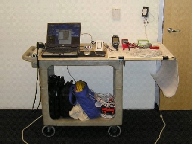
"Commissioning cart" used by RNM Engineering
Description of components of Commissioning Cart
Initialize the addresses
- Connect PDA or laptop to DALI Bus
- Use null-modem cable between RS232 jack on computer and RS232 jack on the Busmaster, or
- Use RS232 jack on computer to DALI-SCI module and connect SCI module to energized DALI Bus, or
- Use USB jack on computer to DALI-USB module and connect USB module to energized DALI Bus
- Run “DALI-Tool” initialize addressing; and
- Resequence the addresses to match design plans; or
- Hand copy initial address onto hardcopy of lighting plans; or
- Drag and drop initial address into corresponding light fixture on electronic lighting plan; and
- Record status of commissioning process on DALI Cx Status Spreadsheet (Excel file)
PDA used to program and control a DALI system
Enter the groups and scenes
- Connect PDA or laptop to DALI Bus
- Run “DALI-Tool” assign groups to ballasts
- Run “DALI-Tool” assign scenes to ballasts